Welding with 3 FANUC robots
Welding with 3 FANUC robots
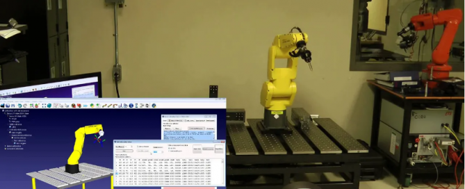
This video shows how you can use our software to weld with 3 Fanuc Robots.
Click here for more informations about -> RoboDK
This video shows how you can use our software to weld with 3 Fanuc Robots.
Click here for more informations about -> RoboDK
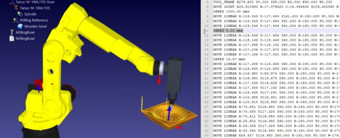
This video shows how you can program your robot to do a fast curve welding.
Click here for more informations about -> RoboDK
This video shows how to calibrate an industrial robot with RoboDK and Creaform’s C-Track Stereo Camera (Optical CMM). RoboDK can be used for robot calibration as well as robot simulation and offline programming. Once the robot is calibrated, RoboDK can be used to easily generate accurate robot programs.
Click here for more informations about -> RoboDK
This video shows how RoboDK can be used to generate paths along surfaces, for example, to generate zig-zag movements for painting applications or inspection.
Click here for more informations about -> RoboDK
The robot Post Processor defines how the robot programs should be generated. The conversion of the simulator movements to specific robot instructions is done by a Post Processor. Post Processors provide complete flexibility to generate the robot programs for specific requirements.
Click here for more informations about -> RoboDK
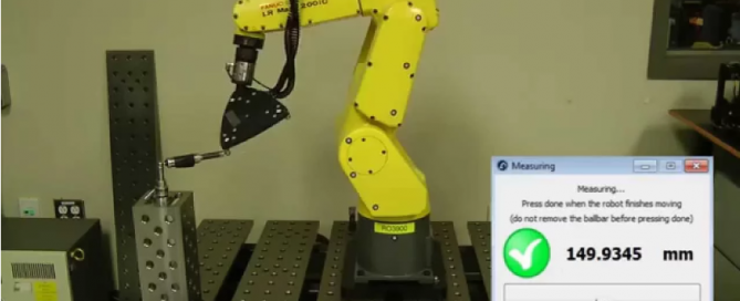
This video shows how to perform a ballbar test to a robot using RoboDK and a Renishaw QC20-W ballbar.
Click here for more informations about -> RoboDK
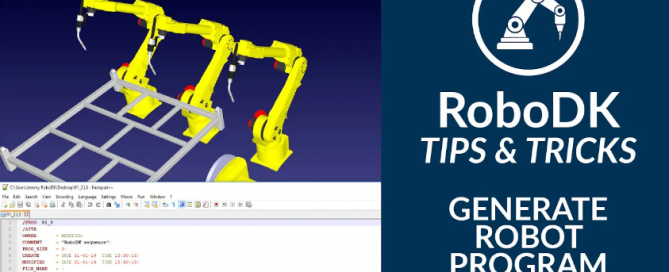
This video shows how you can generate a robot program.
Click here for more informations about -> RoboDK
")
This manual describes parameter settings required to start up our robotic cell Astro-33.
(Legal notice)
(You will find a downloadable PDF version at the end of this page.)
Bring the robotic cell at its place by hand using the heavy-duty handles or with a forklift using the holes provided for this purpose. Make sure it is in the right position.
")
Pull out the rachet handle, secure the four leveling casters to the floor making sure that all wheels don’t touch the floor and that the cell is properly leveled.

Connect the teach pendant to the cable as shown. Rotate the teach pendant it is seated. Then rotate the connector until it is threaded on tight. (Wiggling the connector might let you tighten a bit more.)

You will find the keys for mode selector key switch (T1 / AUTO) in the robot controller.

Connect the main power connector plug to the dedicated power source. Turn on main the cell main power switch which is the controller breaker. Rotate clockwise to turn it ON.
You should now see the green power LED on the Teach Pendant illuminated. Before going further, the controller must warm up at least 30 minutes. After the warm-up time is elapsed, you can go to the next step.
")
First, you must set up a payload. Press MENU, then select 0 for NEXT, select 6 for SYSTEM and finally, 6 for Motion.
")
Enter 0.5 (if nothing on the robot) at line 2 (or your tool payload) PAYLOAD [kg] and press F4 for YES to the question asked.
")
With F1 [TYPE], select 7 DCS.
")
Press F3 for DETAIL, then Press F4 for [CHOICE]. Answer F4 YES to the question to change the setting. Press F4 again and select 2 ENABLE.
")
")
Press MENU, then select 0 for NEXT, select 6 for SYSTEM and finally, select 5 for Config.
")
")
Scroll up to Enable UI Signals: Press F5 for FALSE.


This manual describes parameter settings required to start up our robotic cell Comet-33 and Comet-44.
(Legal notice)
(You will find a downloadable PDF version at the end of this page.)
Bring the robotic cell at its place by hand using the heavy-duty handles or with a forklift using the holes provided for this purpose. Make sure it is in the right position.

Pull out the rachet handle, secure the four leveling casters to the floor making sure that all wheels don’t touch the floor and that the cell is properly leveled. With a level, adjust the height of the leveling caster to properly level the robotic cell.
Connect the teach pendant to the cable as shown. Rotate the teach pendant connector until it is seated. Then rotate the connector until it is threaded on tight. (Wiggling the connector might let you tighten a bit more.)
Connect the EUROMAP 67 connector to the Injection molding machine.

Connect the EUROMAP 73 connector to the Injection molding machine.

Install the tower light with provided screws on top of the cell as shown.
You will find the keys for mode selector key switch (T1 / AUTO) in the robot controller.
Connect the main power connector plug to the dedicated power source. Turn on main the cell main power switch which is the controller breaker. Rotate clockwise to turn it ON. You should now see the green power LED illuminated.
")
Check that each signal of the injection molding machine corresponds to the signal received by the robot controller via the Euromap 67 interface. Close the mold, open the mold, move the ejectors forward and backward. Check each signal sent to the robot controller.

Check that each signal sent by the robot corresponds to the signal received by the injection molding machine via the Euromap 67 interface. Put each BGLogic1 output to on and check if the corresponding signal is on in the IMM interface (HMI).

Release the DCS (Dual Check Safety) by pressing the MENU key, then SYSTEM, DCS. The DCS has been set to restrict the robot from moving more than ±5° on each f his joints. Set all DCS Joint position check to DISABLE. (6 joints position check for the 6 joints of the robot). The status will then change to CHGD instead of SAFE.

Go back to the main DCS page (PREV teach pendant button). Press APPLY and the Code number (master) will be asked. Enter xxxx and press ENTER key. Restart the controller for the changes to be effective. Any changes made by the customer after DCS removal will be at its own risks. To prevent unwanted changes to DCS set up, change the master code at delivery.


This manual describes parameter settings required to start up our robotic cell Satellite-55 and Satellite-66.
(Legal notice)
(You will find a downloadable PDF version at the end of this page.)
Bring the robotic cell at its place by hand using the heavy-duty handles or with a forklift using the holes provided for this purpose. Make sure it is in the right position.

Pull out the rachet handle, secure the four leveling casters to the floor making sure that all wheels don’t touch the floor and that the cell is properly leveled. With a level, adjust the height of the leveling caster to properly level the robotic cell.

Connect the teach pendant to the cable as shown. Rotate the teach pendant connector until it is seated. Then rotate the connector until it is threaded on tight. (Wiggling the connector might let you tighten a bit more.)
Connect the command box as shown. Rotate the cell side connector until it is seated in the command box connector. Then spin the cell connector until it is threaded on tight.

Connect the EUROMAP 67 connector to the Injection molding machine.

Connect the EUROMAP 73 connector to the Injection molding machine.
You will find the keys for mode selector key switch (T1 / AUTO) in the robot controller.
Install the tower light with provided screws on top of the cell as shown.
Connect the main power connector plug to the dedicated power source. Turn on main the cell main power switch which is the controller breaker. Rotate clockwise to turn it ON. You should now see the green power LED illuminated.
Check that each signal of the injection molding machine corresponds to the signal received by the robot controller via the Euromap 67 interface. Close the mold, open the mold, move the ejectors forward and backward. Check each signal sent to the robot controller.
Check that each signal sent by the robot corresponds to the signal received by the injection molding machine via the Euromap 67 interface. Put each output on and check if the corresponding signal is on in the IMM interface (HMI).
Release the DCS (Dual Check Safety) by pressing the MENU key, then SYSTEM, DCS. The DCS has been set to restrict the robot from moving more than ±5° on each f his joints. Set all DCS Joint position check to DISABLE. (6 joints position check for the 6 joints of the robot). The status will then change to CHGD instead of SAFE.
Go back to the main DCS page (PREV teach pendant button). Press APPLY and the “Code number (master) will be asked. Enter xxxx and press ENTER key. Restart the controller for the changes to be effective. Any changes made by the customer after DCS removal will be at its own risks. To prevent unwanted changes to DCS set up, change the master code at delivery.
Copyright 2019 DIY ROBOTICS.
All Rights Reserved.