
Satellite – User Manual

SATELLITE – USER MANUAL
This is a detailed guide to help people with everything related to the Comet robotic cell. This user manual includes critical information about security, maintenance, the robotic cell components, the Teach Pendant controller and about various other topics.
OVERVIEW OF THE CONTENT IN THIS USER MANUAL
SECURITY AND RISK MANAGEMENT
- Operator’s responsabilities
- Security components
- Lockout procedure
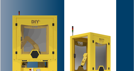
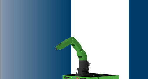
ROBOTIC CELL COMPONENTS
- Robotic cell description
- Fanuc robot
- Lockable side doors
- Tower light
- Command box
- EUROMAP connectors (optional)
- 24V electrical command panel
- Electrical power panel
- Electrical hydraulic lifting system
- Pneumatic system
TEACH PENDANT AND PROGRAMS
- HMI
- Basic programs
- Space check function
- Dual check safety (DCS)
- Alarms
PRODUCTION IN AUTO MODE
- Command panel or box
- Cell door lock procedure
- Starting production in Auto mode
MAINTENANCE
- Procedure for moving the cell
- Fanuc robot

")


